Hacking cars has started to make big headlines in the last years. In this article, I’m going to uncover the basic techniques used in car hacking, review related topics such as embedded software, CAN network, detecting and blocking attacks, and more
Here below a short summary of some key research studies, about security flaws found on real cars and their software solutions :
| Year | OEM | Attack vector | Article |
|---|---|---|---|
| 2015 | Chrysler | Mobile phone remote manipulation | https://bit.ly/3yirW80 |
| 2016 | Tesla | Malicious Wi-Fi hotspot | https://bit.ly/3dKVVfm |
| 2016 | VW | Key cloning Wireless signal | https://bit.ly/3lTXyf5 |
| 2016 | Nissan | Authentication API | https://bit.ly/3rWPQVB |
| 2018 | BMW | Mobile phone remote manipulation Malware attack on USB/OBD | https://bit.ly/3ERqDzi |
| 2019 | MyCar | Hardcoded credentials | https://bit.ly/3rTAAsy |
| 2020 | Mercedes | Mobile App Embedded SIM | https://bit.ly/3dFOMgx |
| 2020 | Toyota | Bluetooth services | https://bit.ly/3pWo9tw |
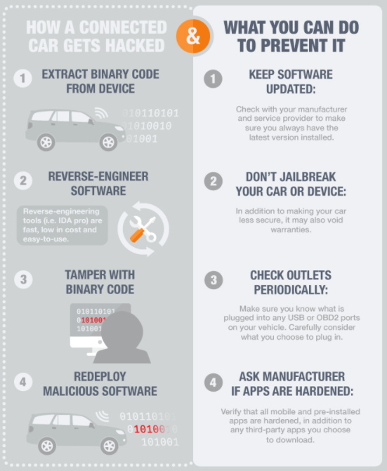
The software manipulations addressed in the above articles, required unique and extensive technical knowledge, prolonged physical access to the target vehicle, and extended periods of time to write code and exploit
Cybersecurity researchers who made these studies have been responsibly disclosing the flaws found, first of all to the OEM, before releasing anything to the general public
The exploitation of these vulnerabilities in the manner developed in these articles, is extremely sophisticated, and the likelihood of such conditions to occur in the real world is therefore limited
However, as more and more softwares are embedded into cars, and vehicles are connected to remote OEM service solutions, the risk to face major hacks can only increase
Now, let’s start our review
Cars are computers with wheels
Today’s cars are very complex equipments
First of all, they are full of sensors/actuators, as without them, a smart car would be totally blind and unable to take control following the driver inputs
These sensors/actuators range from cruise control, wheel speed, tire pressure…to lane departure, rear camera, airbags, and so on
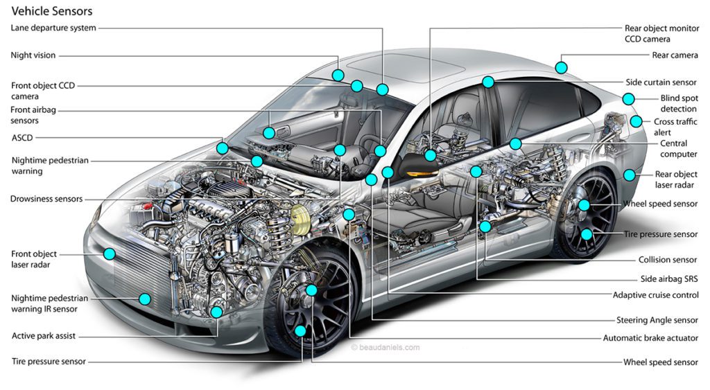
Most of these sensors/actuators are based upon MEMS or Micro Electro Mechanical Systems, and constitute the technology of microscopic devices, particularly those with moving parts
They usually consist of a central unit that processes data – an integrated circuit chip such as a microcontroller – and several components that interact with the surroundings – such as microsensors
MEMS are based upon semiconductor device fabrication technologies, normally used to make electronics, and adapted to their specific requirements
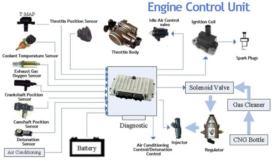
The signals received by the sensors are processed by on board “computers” or ECU, who then relay instructions to the actuators
An electronic control unit (ECU), also known as an electronic control module (ECM), is an embedded system that controls one or more of the electrical systems or subsystems in a vehicle. Some modern vehicles have up to 150 ECUs
Each ECU is connected to several sensors/actuators and electrical systems

ECU with sensors/actuators ECU from Bosch
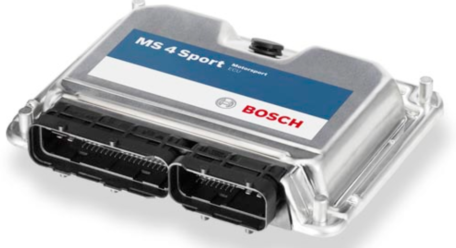
The development of most ECUs is carried out by Tier 1 suppliers based on specifications provided by the OEM
As part of the development cycle of an ECU, manufacturers perform detailed analyses to catch failure modes that can lead to unsafe conditions. Extensive testing and validation activities are carried out to gain confidence in the hardware and software
Within the ECU, are microcontrollers such as the one below from Infineon
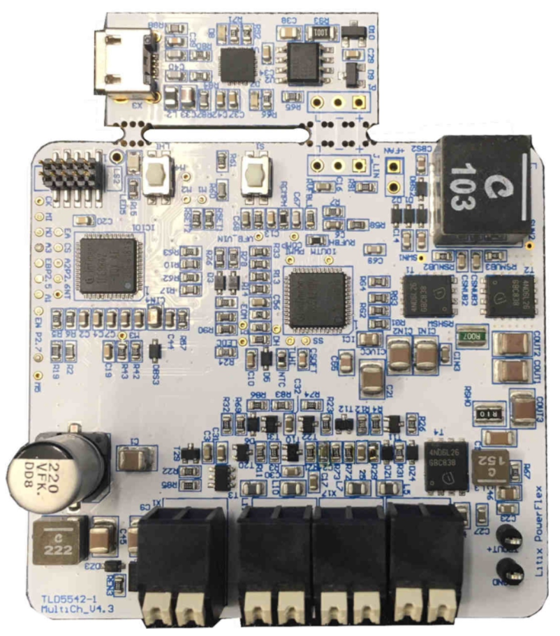
The microcontroller will manage the I/O electric signals (Inputs/Outputs) received from the sensors and to be sent back to the actuators
Flashed into the microcontroller chipset, there is an embedded software, providing all the intelligence to perform the necessary calculations. Let’s go deeper in the following section
Embedded software
First of all, here is a video introduction. It features the Arduino architecture, as it provides a versatile and low cost solution, to start with embedded softwares
Now let’s create a simple embedded software, called the “LED Flasher”. It will blink the LED on our device. It’s a very basic program, it is the “hello world” of embedded softwares
I purchased a Nucleo-64 STM32F103RB microcontroller from ST-Microelectronics, as it provides an affordable and flexible way for users to try out new concepts and build prototypes (https://bit.ly/3pNrwCR)
This board is compatible with Arduino. It is based upon the ARM processor architecture
You can also follow this section without buying the board, as you can run the embedded software in simulation mode (the hardware being simulated). In all cases, you need a Windows PC
IDE basics
We will need an IDE – Integrated Development Environment including the following software components :
Editor : this is where you write the code for your embedded system
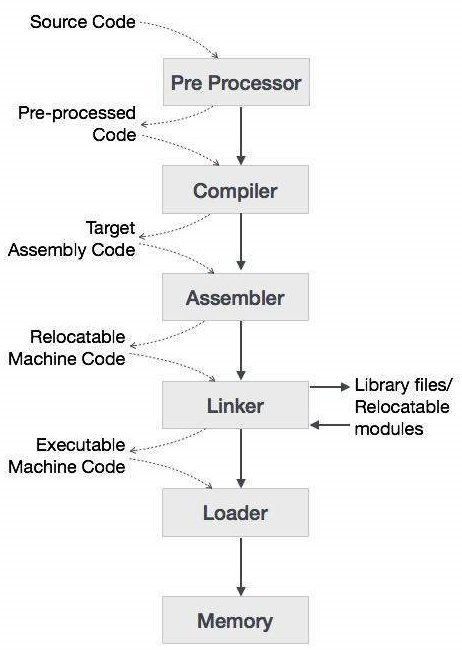
Compiler : it is used when you are done writing your source code. Its function is to convert the source code into object code, which are understandable by computers as it is a low level programming language
Assembler : the function of an assembler is to convert a code written in assembly language into machine language. All the mnemonics and data are converted into op codes and bits by the assembler, as our chipset only understands binary and it works on 0 or 1
Debugger : this is a tool used to debug your code. The debugger goes through the whole code and tests it for errors and bugs, for example a run time error or a syntax error and notifies you wherever it occurs
Linker : it is a computer program that combines one or more object code files and library files together into an executable program. It is a very common practice to write larger programs, into small parts and modules to make the job easier, and to use libraries. All these parts must be combined into a single file for execution, so this function requires a linker
Libraries : it is a pre written program that is ready to use and provides specific functionality. For Embedded Systems, libraries are very important and convenient. Library is a file written in C or C++ and can be used by different programs and users. For example, Arduino microcontroller comes with a number of different libraries that you can download and use while developing your software. For instance, controlling a LED or reading a sensor can be done with a library
Simulation : a simulator helps you to see how your code will work in real time. You can see how sensors are interacting, you can change the input values from sensors, and you can see how the components are working and how changing certain values can change parameters. You can also simulate a target architecture
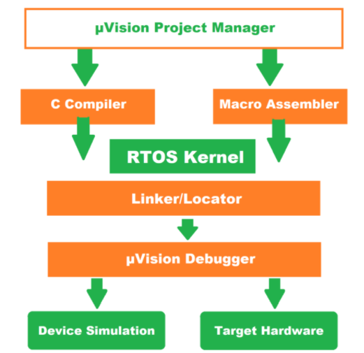
We can select Keil µVision IDE, as this software includes all components : compiler, assembler, linker, debugger, simulator and more. It is compatible with our Nucleo board
IDE Installation
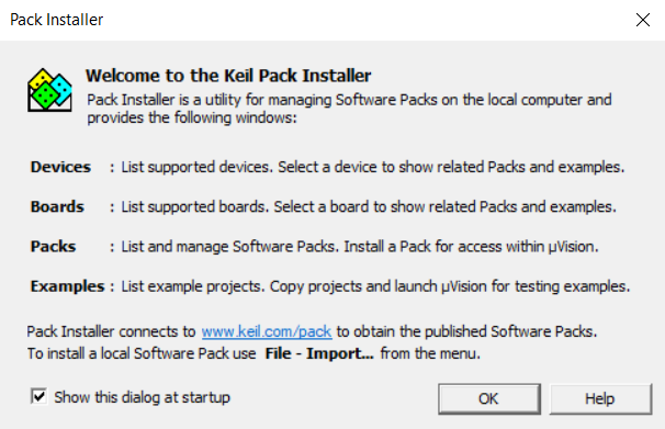
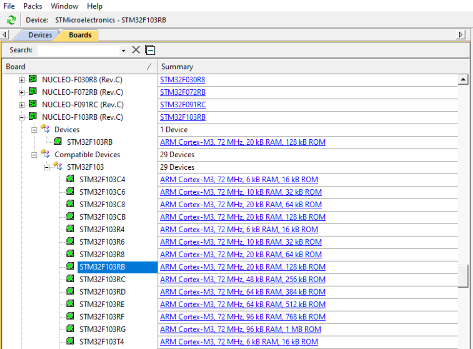
You need to download the ARM Microcontroller Development Kit (MDK-ARM). After installation, you need to specify the devices that you are going to use for coding. For this, launch the Keil Pack Installer
Then, in Devices & Boards, select the correct device : STM32F103RB
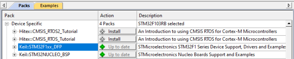
In Packs & Examples, make sure to update the packs :
- Keil::STM32F1xx_DFP
- Keil::STM32NUCLEO_BSP
- ARM::CMSIS
- Keil::MDK-Middleware
To allow communication between the Nucleo board and your PC, you need the Driver Windows ST-LINK/V2 (download from here : https://bit.ly/3pSGNlM)
We are going to use several menus. First of all, navigate in the menus below and understand what they are for

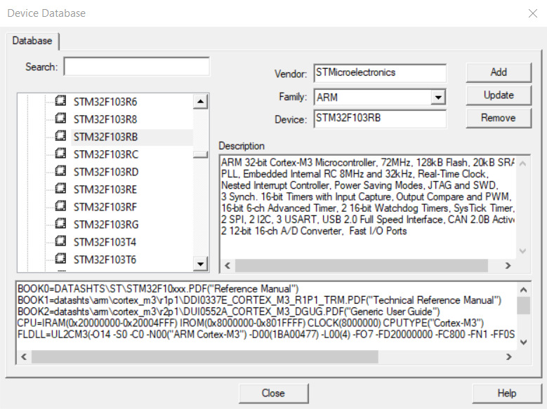
Now we can create a project by clicking : Project -> New µVision Project. We shall choose the correct Device, when prompted to (STM32F103RB)
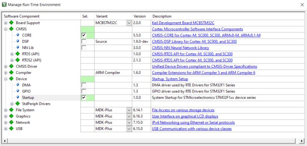
We shall also manage our run time environment, by selecting the following components
Flashing the ROM
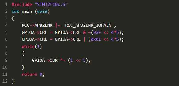
Now let’s create our program and save it into “Blinky.c” (copy the code into Keil : File -> New -> Blinky.c, and then copy the code) . The code is the following (we will explain it later)
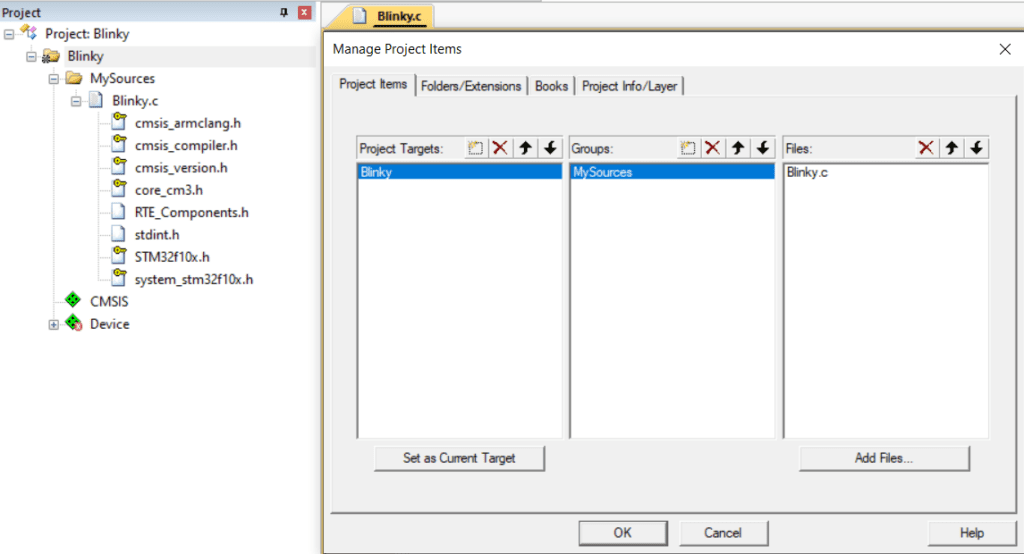
Going to “Manage Project Items”, we can modify the file structure as follows
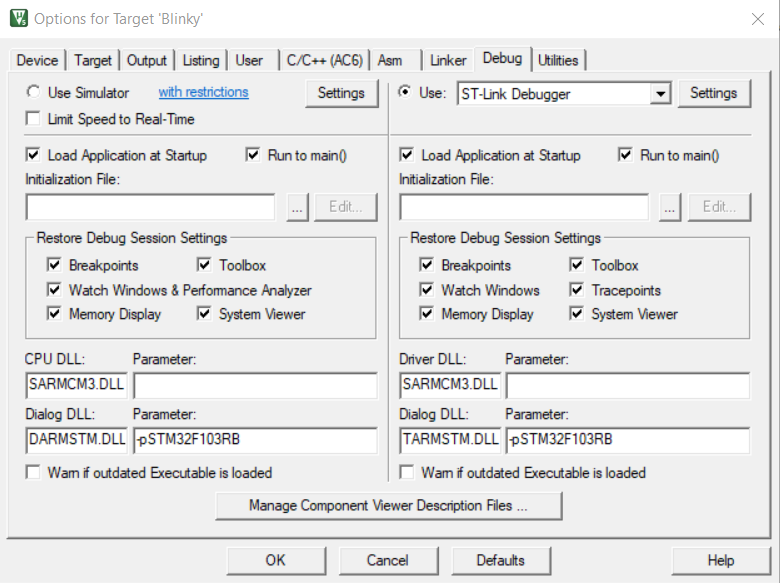
Now let’s plug our board (with a Mini USB Type B cable), and configure the Options for Target “Blinky”. The Debug shall be set to ST-Link Debugger
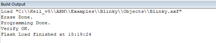
Now, let’s Flash our program into the Nucleo board
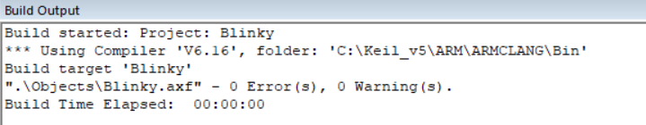
This is a fundamental step as this is going to load our program into the embedded device memory ROM = Read Only Memory. We can see the report confirming that the Flash went ok
We can then Build our program, by clicking on “build”. It will be compiled into a binary code readable by the microprocessor of the Nucleo card
We can Run our program, by clicking on “Start/Stop debug session”. This will instantiate our variables and program steps into the RAM = Random Access Memory
We get to this screen (1: Registers; 2: ARM Assembly code; 3: C code)
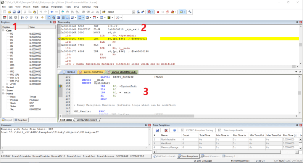
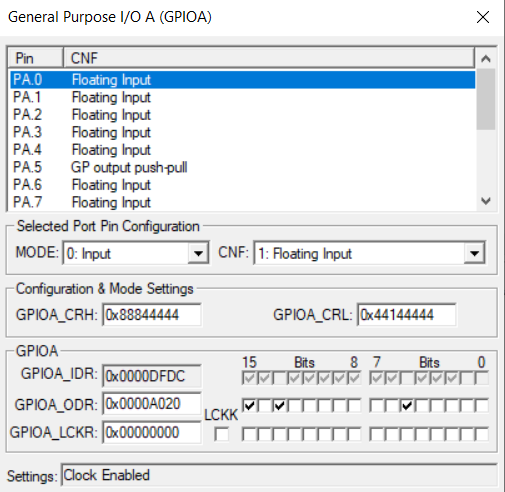
We see our LED blinking on our Nucleo board. During this process, we can see our General Purpose Input/Output GPIO A changing status as it blinks
Let’s explain briefly how the program will execute. The code, loaded into the flash memory or ROM, is interpreted by the Processor. The corresponding Variables will be created into the RAM. The ALU – Arithmetic Logical Unit is performing the necessary calculations, and the program step by step instructions will flow into the Stack
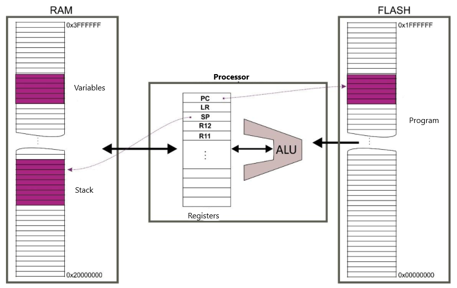
The Registers (R1, R2…SP, LR, PC,…) are storing the necessary data and execution address
Here is a good tutorial about ARM Assembly language : https://bit.ly/33wjUgs
Microcontrollers
Microcontrollers are specific Processors :
- several peripherals are connected to the core : input/output digital ports, analogue-to-digital converters, timers, serial ports (UART, CAN, I²C, Spi, USB…),
- these Peripherals are connected to the Chip through the pins
Our Microcontroller controls these Peripherals, sending to them electric signals, according to the Program instructions (binary)
On Microcontrollers, the Peripherals are configured and controlled through Registers with a fixed and dedicated memory address
That means that the configuration of a Peripheral is done directly into the code, simply by writing or reading into Registers
To Program the Microcontroller, it is therefore essential to read the Reference Manual, as the association between the Registers and the Peripherals will be described in detail in these manuals
The program installed inside an embedded system, is usually called a Firmware (=software installed on a physical device)
Reference Manual
First, here is the Datasheet, which is going to help you make the link between the GPIO and the pins : https://bit.ly/3sCaYk9

Then, here is the Reference Manual, which is the most comprehensive document, where you will find all the necessary informations about the Registers : https://bit.ly/3eqjN8j
Now, let’s look into our code. We can see that the C code deals with the GPIO A, which is the I/O for the LED
ST-Microelectronics library
First of all, we see the include “STM32f10x.h“. This file, developped by ST-MicroElectronics, is important and helpfull. Inside this file, we find :
- C structures defined for a quicker access to the Registers
- Predefined Variables that are storing the address of the Peripherals
Therefore we can write simple instructions such as GPIOA->CRL that is pointing the GPIO A to the Register CRL (L for Low, that means pins from 0 to 7)
C code explained
- The first instruction in the main is RCC->APB2ENR |= RCC_APB2ENR_IOPAEN. This code activates the clock and timer on the chip (as it is not activated by default for energy savings)
- Then, the two lines GPIOA->CRL are here to control the output pin n°5 of GPIO A (this is the LED of our board, as per the Reference Manual)
- while(1) is a condition that is always TRUE, so this is an infinite loop
- Finally, the GPIO->ODR has a XOR that compares bit to bit 1 and 5, this turns either to 0 and 1 and make the LED blink
With this basic example, we see that microcontrollers can be very convenient devices and turn an ECU into a computer that is going to send electric signals to the relevant peripherals
Let’s wrap-up some of the skills needed to program a microcontroller and ECU

ECU and microcontrollers, together with their embedded software, are obviously very important, as they provide the computing to trigger the electrical signals from/to sensors and actuators
To operate together, the ECU need to be interconnected or multiplexed with the CAN Bus. Let’s review this now
The CAN bus
A Controller Area Network (CAN bus) is a vehicle bus standard designed to allow microcontrollers and devices to communicate with each others without a host computer
It is a message-based protocol, designed for multiplex electrical wiring. It simplifies wiring, improves reliability, and facilitates vehicle diagnosis via the On-Board Diagnostics (OBD)
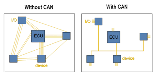
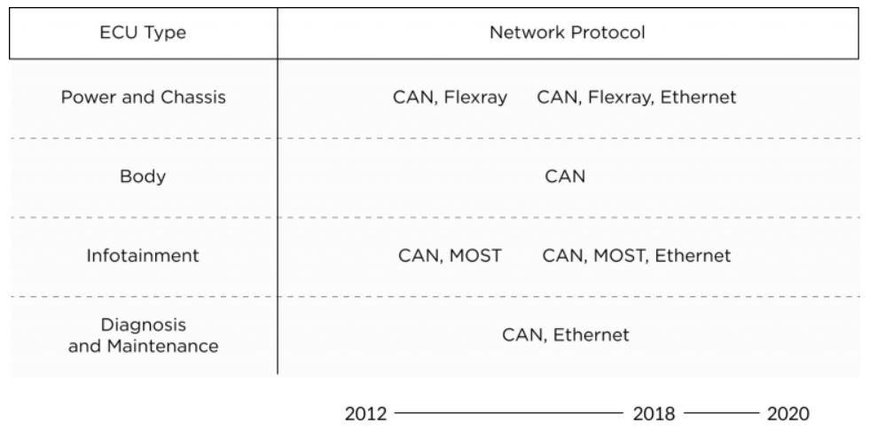
In practice, the CAN bus is split into several networks with some specific protocols in use, according to the areas covered (powertrain, body, infotainment,…) : CAN, FlexRay, MOST, Ethernet
The data is transmitted sequentially in a frame, but in such a way that if more than one device transmits at the same time, the highest priority device can continue while the others back off
Frames are received by all devices, including by the transmitting device
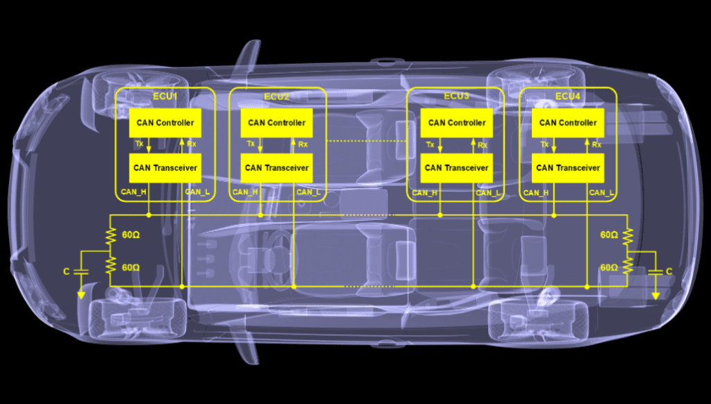
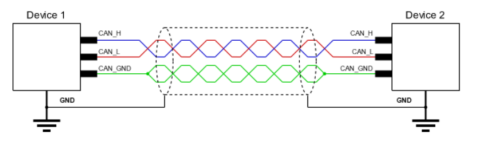
The CAN bus wiring is made of two cables CAN_High and CAN_Low. The difference in tension between the two cables forwards the relevant electrical signal to the ECU
The CAN bus frame is made of eight protocol message fields. Two of them – CAN ID and Data – are important when recording CAN bus data
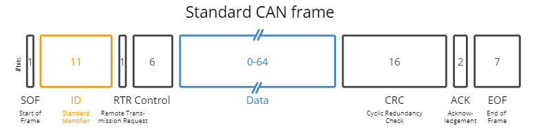
- SOF (Start of Frame) : marks the beginning of data and remote Frames
- Arbitration Field : includes the message ID and RTR (Remote Transmission Request) bit, which distinguishes data and remote frames
- Control Field : used to determine data size and message ID length
- Data Field : the actual data
- CRC Field : checksum
- EOF (End of Frame) : marks the end of data and remote frames
Here is an example of CAN bus record : https://bit.ly/3Ecly3J
Simulation of a CAN bus
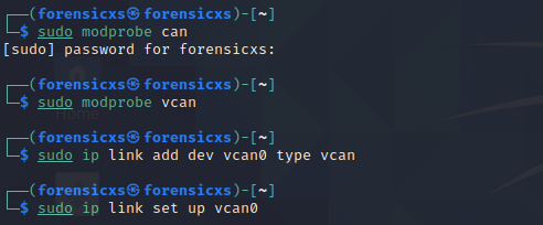
We can simulate a CAN bus network on Linux (I use Kali Linux). First of all, we start-up the kernel for the CAN bus and also the virtual CAN bus, and also set-up the IP address interface
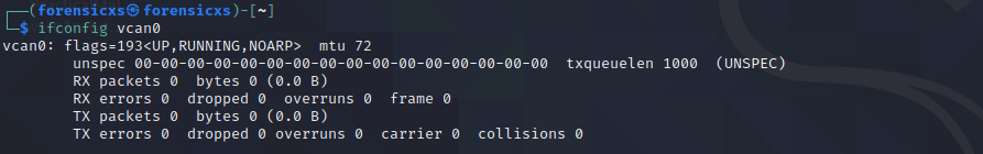
We can check that our network interface is up and running
We are now ready to send and receive CAN frames. We can simulate CAN messages using the cangen command on our virtual network (cangen vcan0)
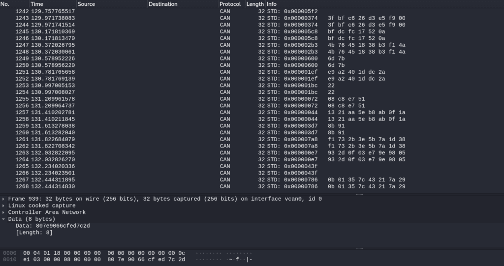
We can see the flow of can frames when launching Wireshark
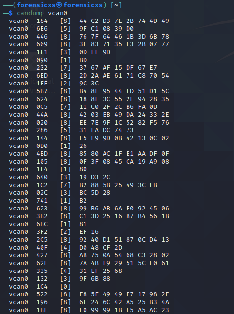
We can also get a dump of the CAN frames by using the command candump, and also log it with candump -l
The frames can be replayed using the command canplayer -I
It can be especially usefull when trying to modify frames and replay a sequence into the CAN bus
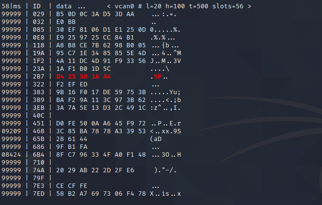
You can use also cansniffer -c to check any modifications to the frame between one and another (changes will be highlighted in red)
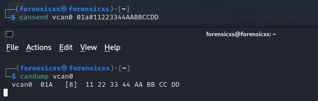
Another usefull command is cansend, we can send a frame from a Linux terminal and receive it in another terminal
There are other usefull commands detailed in the can-utils library : https://bit.ly/3EnWrLr
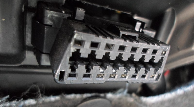
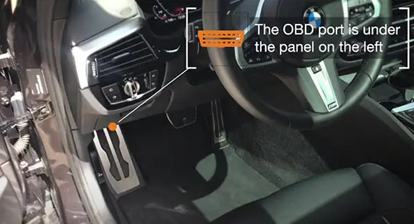
OBD
On-board diagnostics (OBD) help provide specific data related to which system or component failed or caused a failure during run time, and greatly help perform repairs
There are many types and brands of diagnostic tools available on the market, either from the OEM or from third parties
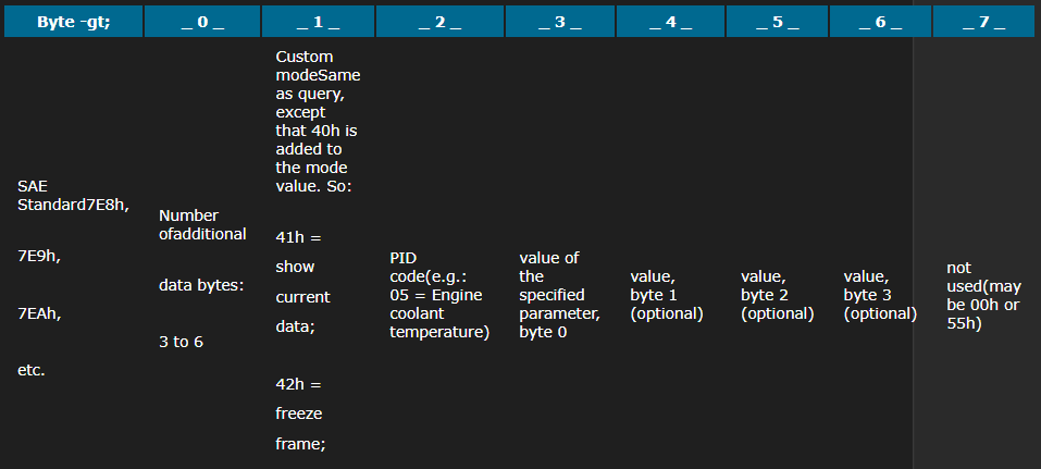
The OBD uses an SAE protocol – Society of Automotive Engineers -, based upon some PID – Process Identifier -, each standard action used in the OBD tools corresponding to a specific PID
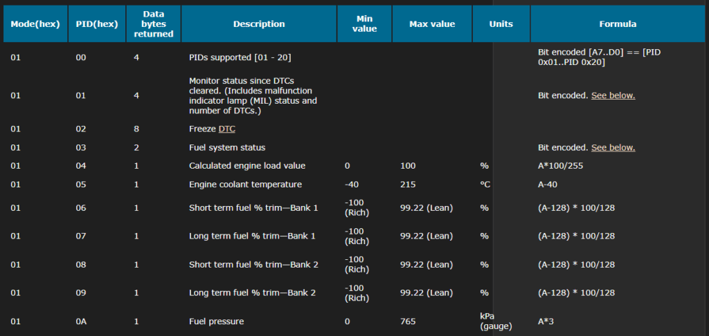
The PID are triggering standard CAN bus messages, and in turn, the ECU are sending back the necessary messages to the OBD tool, with a status about their respective situation. The vehicle responds to the PID query on the CAN bus with message IDs that depend on which module responded
Simulation of Car Hacking
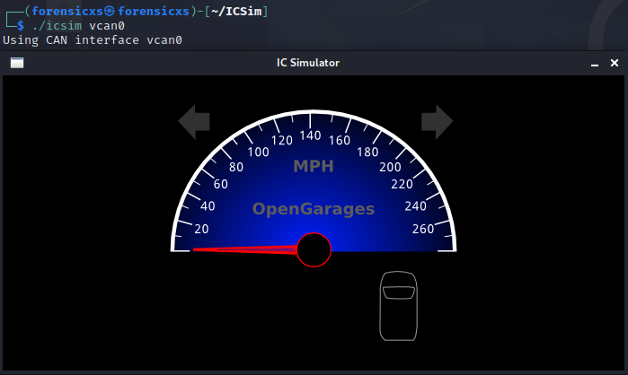
I’m going to use the Instrument Cluster Simulator (ICSim) : https://bit.ly/3pbbkfz
It was developed by Craig Smith at Open Garages. He is the author of “The Car Hackers Handbook” (No Starch Press) : https://bit.ly/33C5xap
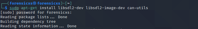
First of all, we must install some dependencies, including can-utils if not yet installed in your Linux version, and SDL which is a cross-platform development library for computer graphics and audio : https://www.libsdl.org/
Since ISCim draws and animates a virtual dashboard, this is required
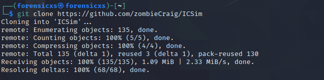
Then, we clone the github repository of ICSim
Here are the files available in the ICSim repository
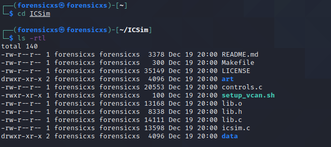
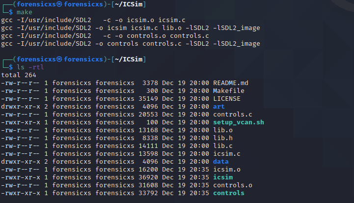
We notice that the executable icsim is “missing”. We easily fix this with the “make” command
Let’s start the simulator on our virtual CAN network
We also launch the control panel
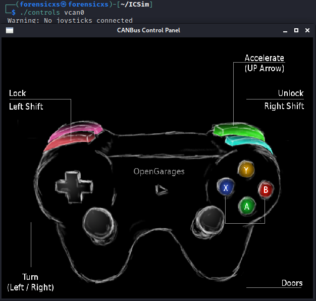
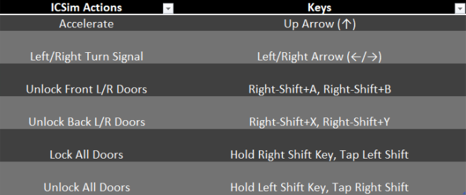
If you don’t have an XBOX controller, it is possible to apply the controls with the keyboard. All buttons are functional and we can see the vehicle reaction simulated (acceleration, turns, door lock)
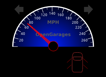
For example, here is the sim at 70 mph and all doors unlocked
We can launch cansniffer : cansniffer -c vcan0
We see a very fast flow of data in the CAN bus
Now we can play with the key strokes and try to identify patterns in the bus data corresponding to our key strokes. It is not easy. So, I used a handy tool called Kayak : https://bit.ly/3yST8KQ
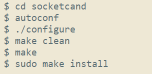
We must first install socketcand : https://bit.ly/3yQsnH2, which is a daemon that provides access to CAN interfaces on a machine via a network interface. The communication protocol uses a TCP/IP connection and a specific protocol to transfer CAN frames and control commands
For this installation, I found out that a file is missing in the repository : config.h.in
You can take it from here : https://bit.ly/3JgiMOo
Then proceed with the installation of socketcand : https://bit.ly/3JdszES
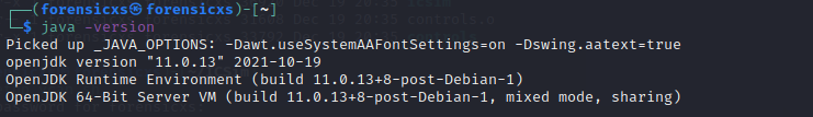
Kayak being based upon Java, it needs the OpenJDK to run (Java Standard Edition which is Open Source). To check if Java SE is installed on your Linux, type java -version
If Java is not installed, it will take you several steps : https://bit.ly/3qjci8L
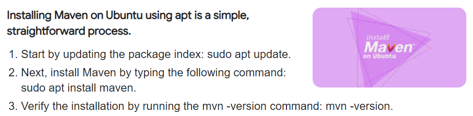
Then, we install Maven (it’s a software comparable to the Make command of Linux, it allows to build a Java software from its sources)
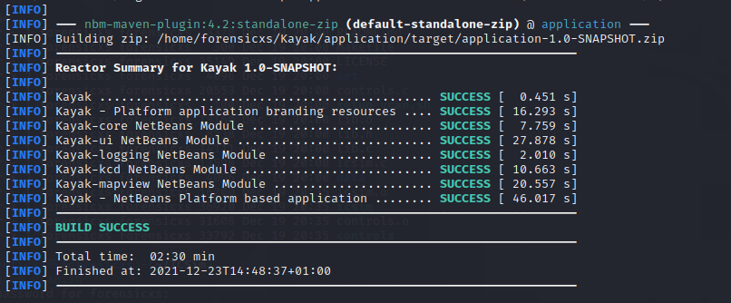
With Maven installed, we can build Kayak (inside the Kayak source folder). All dependencies are downloaded during the build process (it takes quite a while)
Before launching Kayak, we must start socketcand

Now we can start Kayak
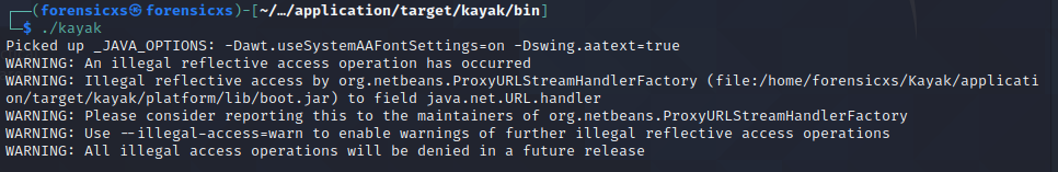
We just need to follow the start screen instructions and we are done
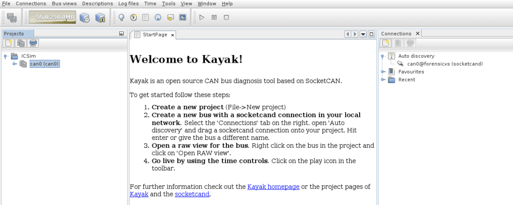
Then, start the live stream (grey arrow). We see data coming into Kayak
From now on, we can check various interactions with the control panel of ICSim and “sniff” the data flow in Kayak. It is much more convenient than checking the flow of data directly into the CAN interface
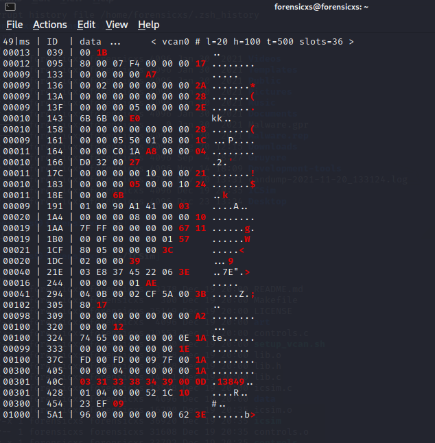
After some time playing around, we can derive the IDs associated to each device, in particular the 5 bytes of data from the tachymeter
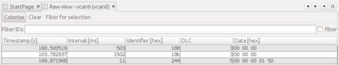
Here is a summary table of our observations
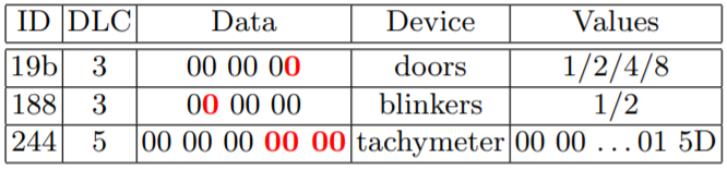
The data highlighted in red, are the hexadecimal numbers that are seen changing for each device ID
For example, the tachymeter ID244 changes the last two bytes during a driver input on the accelerator. The allowed speed range of 0-100 mph is triggered by hexadecimal data values ranging from 00 00 to 01 5D
It can also be seen that there are four possible values transmitted to operate the doors ID19b (one per door) and two for the blinkers ID188
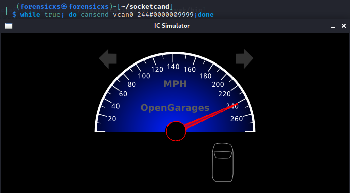
For example, we can fuzz the tachymeter at a high speed of 240 mph with this simple script
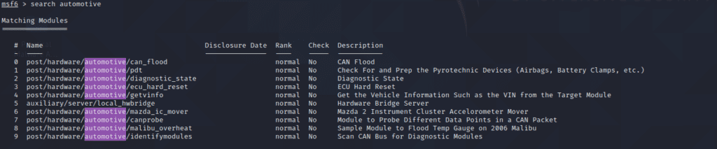
Metasploit
Here the Metasploit installation instructions : https://bit.ly/3JgC1ri. After installation, we launch it using the msfconsole command. Then we can look for the Automotive modules
There is a good article that shows you how to use these modules : https://bit.ly/3FBm8Ju. First of all, you need to set-up the hardware connection, then you can use one of the attack modules
If you want to learn more about these modules, you can look into them. They are written in Ruby. You can find them in the GitHub repository : https://bit.ly/33YoVil
For example, here is what is under the hood for the module canprobe.rb. It is apparently a simple blind fuzzer
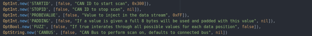
These modules are currently very limited in scope, but any talented hacker could craft attack modules as per the need
Real world Car Hacking
We have seen in this simulator that we can correlate actions from the driver (ex: acceleration), with the bus frame ID number, and the frame data. We could therefore craft specific commands and “hack” the car
In real life, it will be much more difficult. There are several key issues :
- OBD ports may not give you a direct access to the CAN bus you are looking for
- The CAN bus quantity of data is huge and the data are sent very fast
- The bus data may be obfuscated as arbitration identifiers are often used
Let’s explore some topics that are relevant for real world car hacking and security, on which researchers and industry practicioners are currently focusing
Car tuning
It is important to know that Flashing off Engine ECU and related stuff is a very well known practice, especially in the USA where there is a high demand for super duty cars/trucks (such as the Ford F550)
The truck community is quite often tuning trucks, for increased engine power and so on. There are software and hardware vendors specialized in this tuning industry. They rely on security keys licenced by the OEMs
Here is an example in this video, with the hardware/software package from EFI Live, applied on a Chevrolet Silverado
There is going to be a future obvious contradiction between the need for secure cars and enthusiastic car modding
On one side, we want to secure all this, but we also need to make good tools available to legitimate repairers. But anybody can be a legitimate repairer including malicious people
Here is a good article covering this : https://bit.ly/3qoqc9V
Seed to key algorithm
These algorithms are in use on cars, to make sure that any diagnostic tool trying the connect to an ECU, is allowed to do it “by design”. The protection mechanism is the following :
- the diagnostic tool sends a security access request
- the ECU responds with an ID and a pseudo-random challenge
- the diagnostic tool references the ID against a database of ECUs and their security keys
- the diagnostic tool calculates and sends a response back to the ECU (key challenge)
- the ECU compares this to its own key challenge calculation and enters into the desired run mode if there is a match
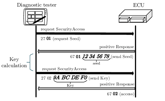
Here is more information about the mechanism : https://bit.ly/3Je3Dx0. An example of a seed algorithm is given here below (based upon some XOR and bit offset)
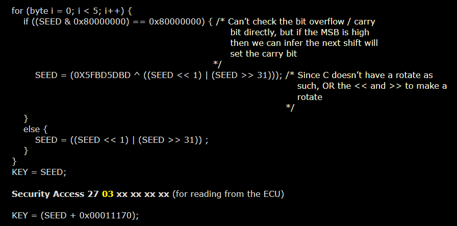
In fact, by intensive semi-automatic trials, it could be possible to retrieve the seed-key algorithm, as is documented in this research study : https://bit.ly/3HjVlSJ. The hashing functions being used are not cryptographically secure
Here is further reading on reversing a seed-key algorithm : https://bit.ly/3yVJHKF
The Flashing of the ECUs is also protected with the seed-key algorithm, so potentially lacks security
Attacks on the CAN bus
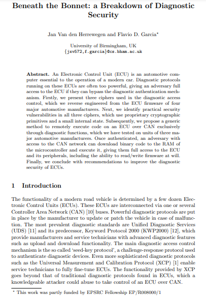
This report is really comprehensive and provides an in-depth review of CAN protocols applied in many OEM brands : https://bit.ly/3z5UbYa
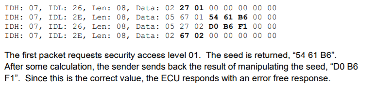
First of all, the report explains how to craft CAN frames for :
- diagnostic session control
- security access
- request download and upload
Second, it shows the complexity to craft fake frames to the CAN bus :
- most ECU include protections and are not going to accept values beyond some security limits
- frames that actually control some functions of the vehicle, are quite hard to identify as related to the exchange of data between some specific ECUs, or sent through another CAN bus
- the car is still sending legit frames while you try to send faked frames, and the ECU may not be able to follow your frames for priority reasons
- the security seed will change after a limited number of invalid challenge responses, so brute forcing in real-time is extremely impractical

Nevertheless, the report provides, for some specific vehicles, examples of faked messages and the reaction onto the car. The technical aspects are quite advanced :
- finding a way to download instructions on the ECU
- writing code, translating it into machine code for execution on the CAN
- reprogramming the ECU in some way through calibration update
It also proposes a process for detecting attacks based on frequency :
- unusual CAN frames are going to be exceptional or flooding the CAN bus, contrary to common packets which tend to reproduce at a regular and predictable frequency
- attacks stand out greatly from normal CAN traffic and could easily be detected
- a system can detect CAN anomalies based on the known frequency of certain traffic and can alert a system or user if frequency levels vary drastically from what is well known

Here is an Intrusion Detection System (IDS) proposed as a commercial solution, helping to protect the CAN network from potential intrusions, and avoid faked messages to be spread over the CAN network
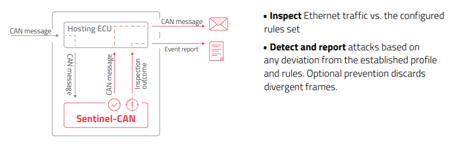
The IDS enables to define factory settings for each microcontroller, and create a whitelist of permitted binaries, processes, scripts and network behavior
The IDS would detect and block attempts to download and run unauthorized code on the ECU, allowing the execution of only specified code and applications
Finally, the IDS can be embedded into controllers during the development process, and it can also be installed on existing vehicles during regular maintenance
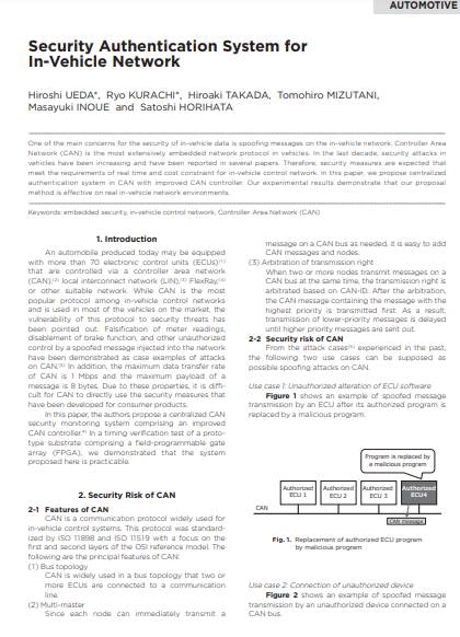
CAN Security Authentication
Further security measures are expected in CAN, but they shall meet the requirements of real time and cost constraint for in-vehicle control network
Also, the CAN has a small frame payload size, and this is a natural limit for strong cryptography
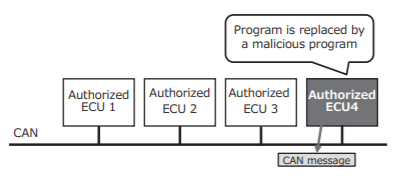
But, we definitely want to avoid the situation where a malicious program is injected into an ECU and this ECU could operate undetected
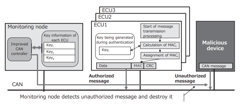
As a potential solution, in the paper below, is proposed a centralized authentication system in CAN, based upon a HMAC cryptographic protocol : https://bit.ly/3qzEULo
In the event that an ECU has been corrupted, the encryption system shall block the exchange of CAN messages with this ECU
The use of this algorithm provides a significant improvement, but we are still far away from a very strong encryption, as this would be very costly in terms of speed of the network, and impact the “real time” performance of the CAN bus
A further step could be to use a Certificate Authority, combined with an Access Control List (ACL), and a secured connection to the OBD
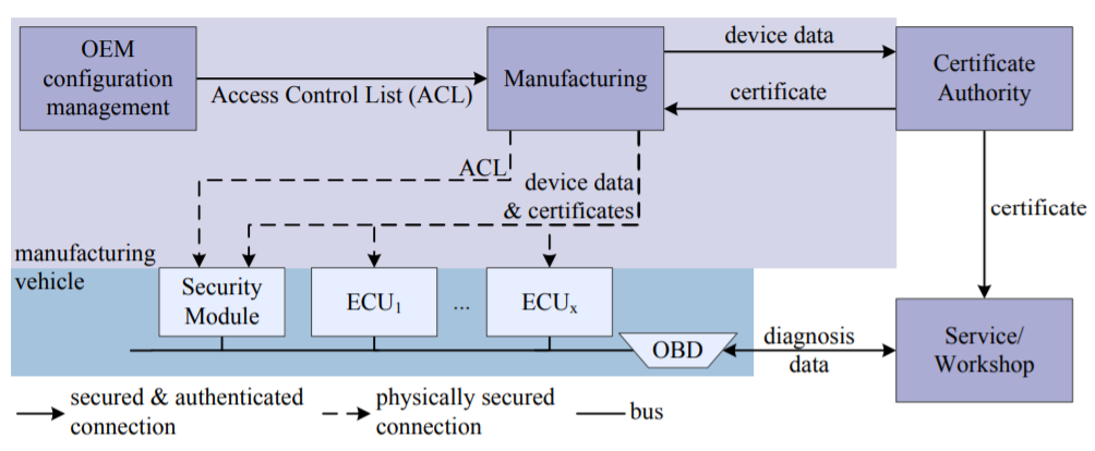
Remote firmware updates
It is quite obvious that a compromised ECUs can have a severe impact on vehicle operational safety. Therefore, the way that firmware updates are distributed shall be secured
Especially, Over-The-Air (OTA) updates are the most prone to cyberattacks
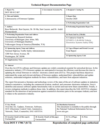
The paper below explores the general concepts behind safe remote firmware updates : https://bit.ly/3Fzim3o
Here are in summary, the recommendations from this report :
SoC architecture
- the ECU embedding a SoC – system on chip-, shall partition the bootloader from the firmware OS and the application data
- the hardware should include a physical security module or HSM – Hardware Security Module -, for secure private key storage and accelerated cryptographic operations
- the bootloader should be using the more secured UEFI mode – Unified Extensible Firmware Interface – instead of BIOS
- the OS should include a secure boot mechanism
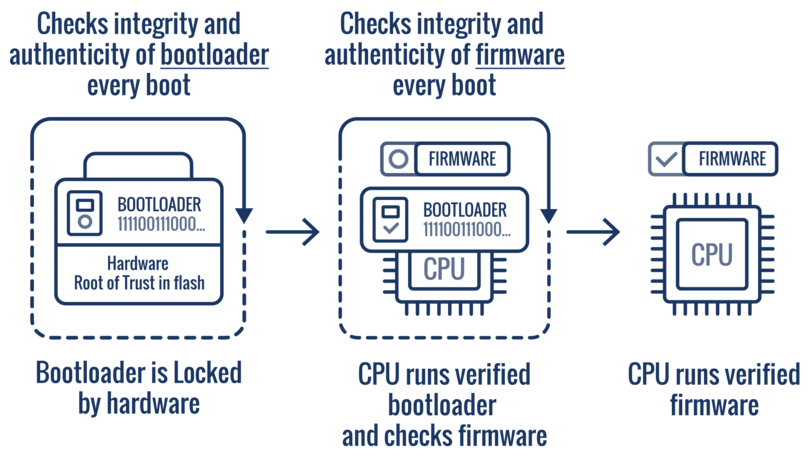
Secure boot
- enables a chain of trust to dispatch the update
- safeguards the boot chain, ensuring that only original firmware is loaded
- based upon a secure channel relying upon authentication and encryption
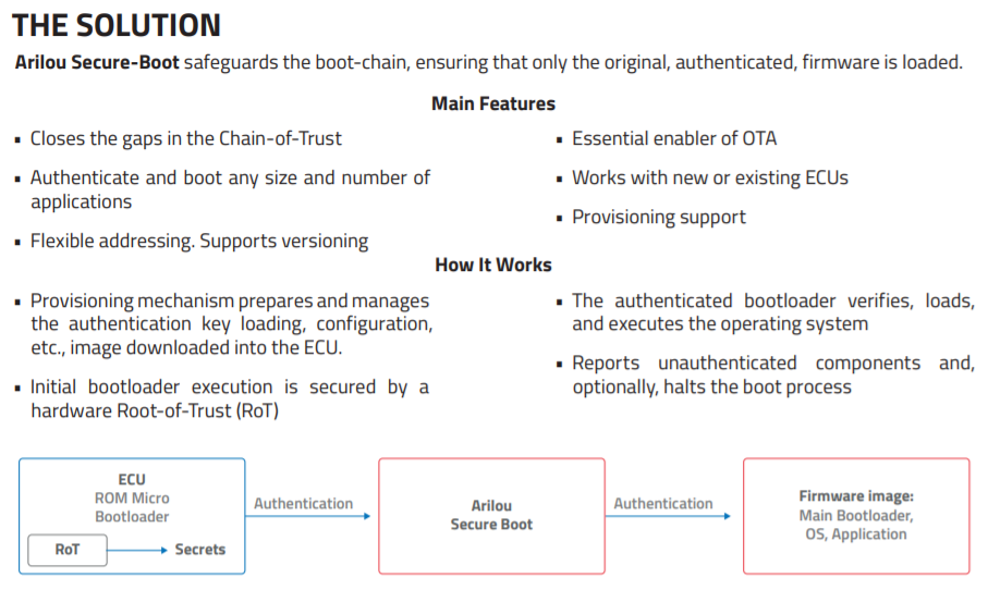
Here is an example of a commercial solution
Remote car hacking
There was a comprehensive research study in 2015, looking into the systems of the Jeep Cherokee : https://bit.ly/3zfRtiV
The researchers made a detailed reversing of the Uconnect infotainment system from Harman (Samsung). This system is embedded in many modern cars
Uconnect is based on the UNIX like QNX OS from Blackberry. The Cherokee also has a cellular connection from Sierra Wireless 3G through the Sprint network. The researchers performed a set of complex actions, to take control of the vehicle (to some extent) :
Access over the cellular network
- implementation of a femtocell
- scanning port and IP range for vulnerable vehicle
- discovery of network settings and open ports
- discovery of vulnerable D-bus services (https://bit.ly/3sMEB2z)
- connection through SSH
Jailbreak of Uconnect
- reverse engineering of the firmware and CAN functions (this usually implies bypassing an anti debugging safety)
- identification of vulnerabilities (memory corruption, stack overflow)
- hand editing the ISO file in a HEX editor
- altered integrity check byte
- putting the ISO on a USB stick and flashing the modified software
- bypassing the validation checks
- gaining code execution
Shell commands into D-bus
- crafting attack scripts
- input of arbitrary commands in the inter-process services
- exploitation of the D-bus
- dispatch of arbitrary CAN data
- taking control of ECUs
The researchers disclosed the vulnerabilities to Chrysler. The car manufacturer decided to recall 1.4 million vehicles for safety reasons, although the risk to reproduce such attacks were minimal
Among the countermeasures, some ports were blocked and modifications on the Sprint network were made, to deter potential attacks
There is a good report exploring similar topics, but on a Mercedes : https://bit.ly/30YZwnt

Conclusion
We started this article by covering the basics of cars embedded softwares and networking through the CAN. For a better understanting, we have played with some tools :
- an ARM Nucleo board on which we flashed a first program
- the CAN-utils library and the ICSim simulator
Therefore we could gain a deeper knowledge about microcontrollers, ECU, CAN bus, OBD plug and more
We then covered some key security topics in the real car market :
- seed to key algorithm
- attacks on the CAN bus
- CAN security authentication
- remote firmware updates
- remote car hacking
Due to the continuous growth of telematics and infotainment on-board our cars, the safety countermeasures will be even more necessary. The OEMS are putting a priority on this, as more stringent cybersecurity norms, the risk of costly recall campaigns and potential accidents, are putting pressure on them
The contradiction between the need for protection, but at the same time allowing car maintenance and troubleshooting with tools available to the population, will be a hot topic
Last but not least, we will see the emergence of Ethernet based networks on-board our cars